1. Why Single-Phase Runs Multiply One-Way Distance by 2
Current in a single-phase AC or two-wire DC branch circuit travels out to the appliance on the ungrounded hot conductor and returns to the panel on the neutral or negative conductor—doubling the effective copper or aluminum path length.
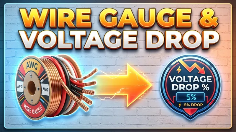
Accordingly, single-phase and DC voltage drop follows V_drop = 2 × OneWayLength × Current(A) × ResistancePerUnitLength, whereas balanced three-phase circuits use V_drop = √3 × OneWayLength × Current(A) × ResistancePerUnitLength.
- Recommended branch-circuit target: ≤ 3% voltage drop from panel to farthest outlet
- Combined feeder + branch target: ≤ 5% total drop at full continuous load
- 10 AWG uncoated copper reference DC resistance (75°C): ~1.21 Ω per 1,000 ft
2. Ampacity, Continuous Loads & Service Panel Upgrades
Even if voltage drop falls below 3% on a short run, conductor gauge must still meet safe thermal ampacity limits and breaker protection rules. Continuous loads running 3 hours or more (such as EV chargers or electric tankless heaters) require conductors and breakers rated at 125% of continuous current.
Before adding high-draw HVAC compressors or EV circuits to an older 100A panel, run a preliminary connected-load summary and schedule an official load calculation with a licensed electrical contractor.
Technical References & Standards Basis
- NEC Chapter 9 Table 8 — Conductor Properties & DC Resistance
- NEC Article 210 / 215 Informational Notes on 3% and 5% Voltage Drop